Introduction
A mismatched flange — wrong pressure class, wrong facing, wrong end connection — can mean a failed joint under operating conditions, an unplanned shutdown, or a safety incident. Flanges connect pipes, valves, pressure vessels, and equipment across every stage of oil and gas operations, and the selection criteria vary significantly by application.
Not all flanges perform the same way under high pressure, thermal cycling, or corrosive media.
This article covers the six most common flange types used in oil and gas, what makes each one distinct, and how to match the right type to the right application.
Key Takeaways
- A flange is a mechanical connector that joins pipes, valves, and equipment, creating secure, leak-resistant, and removable connections
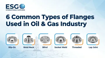
- The six most common types are Weld Neck, Slip-On, Blind, Threaded, Socket Weld, and Lap Joint
- Weld Neck flanges dominate high-pressure and high-temperature applications; Blind flanges seal pipeline ends; Slip-On flanges suit lower-pressure systems
- Right flange selection hinges on operating pressure, temperature, pipe size, material compatibility, and how often the joint needs to be broken
- Wrong flange selection risks joint failure, unplanned downtime, and serious safety hazards
What Is a Flange in the Oil & Gas Industry?
A flange is a flat, circular mechanical disc, typically forged or cast from steel alloys. Two flanges bolt together with a gasket in between, forming a sealed, pressure-rated joint that connects pipes, valves, and vessels in a piping system.
Industry standards govern every dimension of flange design, covering:
- Pressure-temperature ratings — what the joint can safely handle under operating conditions
- Material grades — carbon steel, stainless, alloy, and specialty metals
- Face types — raised face, flat face, ring-type joint, and others
- Dimensional tolerances — ensuring parts from different suppliers fit precisely
ASME B16.5 covers pipe flanges from NPS ½ through NPS 24, while ASME B16.47 addresses large-diameter flanges from NPS 26 through NPS 60. This standardization ensures interoperability across suppliers and job sites — a critical requirement in oil and gas operations where unplanned downtime carries significant cost.
ESG International Suppliers stocks flanges built to ASME specifications, supplying oil and gas operations across North and South America.
Why Proper Flange Type Selection Matters in Oil & Gas
Oil and gas piping systems transport hazardous fluids (crude oil, natural gas, hydrogen sulfide, and other corrosive or flammable media) under extreme conditions. A mismatched or improperly specified flange can result in leaks, fires, unplanned shutdowns, or regulatory non-compliance.
What goes wrong with the wrong flange type:
- Using a Slip-On flange where a Weld Neck is required for cyclic stress can cause fatigue cracking
- Socket Weld flanges in corrosive service accelerate crevice corrosion at the internal gap
- Choosing an overly complex flange where a simpler one suffices inflates project cost unnecessarily
The U.S. Chemical Safety Board documented a hydrogen gas release and fire at the CITGO Sulphur, Louisiana refinery causing over $1.5 million in property damage. The root cause? A flange leak on a heat exchanger from relaxed bolts and incorrect torque specifications.
Flange type selection is an engineering decision. Operating conditions, maintenance frequency, pipe size, pressure class, and fluid characteristics all factor into getting it right.
6 Common Types of Flanges Used in the Oil & Gas Industry
While many flange variants exist, six types dominate oil and gas projects globally because they cover the full spectrum of operating conditions — from vacuum to extreme pressure, from small-bore instrument lines to large-diameter process headers.
Weld Neck Flange
What it is and how it works:
A Weld Neck flange features a long, tapered hub that transitions gradually into the pipe wall. It is connected via a full-penetration butt weld, which creates a continuous, uninterrupted flow bore and distributes mechanical and thermal stresses evenly across the hub and into the pipe.
Where it performs best:
Weld Neck flanges are the standard choice for:
- High-pressure services (Class 600 to Class 2500)
- High-temperature applications
- Cyclic or fatigue-prone services
- Process headers, offshore wellhead piping, and refinery reactor circuits
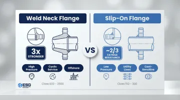
Research shows Weld Neck flanges offer approximately three times the fatigue life of Slip-On alternatives under ASME B16.5, making them the strongest joint available. The tapered hub prevents bending stress peaks and distributes loads evenly.
Key limitation:
Weld Neck flanges require skilled butt-weld execution, precise pipe alignment, and radiographic inspection — making them more expensive to procure and install. For low-pressure utility systems, this investment is rarely justified.
Slip-On Flange
What it is and how it works:
A Slip-On flange has a bore slightly larger than the pipe's outer diameter, allowing it to slide over the pipe end. It is secured with two fillet welds — one on the outside of the flange and one on the inside face.
Where it performs best:
Widely used in:
- Lower-pressure applications (typically Class 150 and Class 300)
- Utility piping and water systems
- Non-critical process lines where cost control and ease of installation are priorities
Engineers favor Slip-On flanges because alignment is forgiving and the procurement cost is significantly lower than Weld Neck flanges.
Key limitation:
Because Slip-On flanges rely on fillet welds rather than full-penetration butt welds, they offer lower fatigue resistance — calculated strength is approximately 2/3 that of a Weld Neck flange. ASME B31.3 states they should be avoided where many large temperature cycles are expected. They are not recommended for high-pressure, high-temperature, or cyclic load services.
Blind Flange
What it is and how it works:
A Blind flange is a solid disc without a bore. It is bolted onto the face of an open pipe end, vessel nozzle, or valve outlet to create a complete pressure-retaining seal — terminating flow while allowing future access by simply unbolting and removing the blind.
Where it performs best:
Blind flanges are essential for:
- Isolating pipeline sections during maintenance, pressure testing, or inspection
- Terminating vessel nozzles and providing access covers
- High-pressure services (rated across all ASME pressure classes, including Class 1500 and 2500)
That combination of isolation capability and pressure-class flexibility is why Blind flanges appear on virtually every oil and gas project, from small instrument headers to large process vessels.
Key limitation:
In larger diameters and higher pressure classes, Blind flanges become very heavy and require significant bolt-up force to maintain a tight seal. The absence of a bore means they do not permit flow measurement or cleaning access — they must be removed completely to restore flow.
Threaded Flange
What it is and how it works:
A Threaded flange has an internally threaded bore that mates with the external threads on the pipe end. The flange is simply screwed onto the pipe without any welding, making it the quickest connection type to install in the field for small-diameter lines.
Where it performs best:
Used in:
- Low-pressure utility services (air, water, steam utility lines)
- Instrument connections
- Small-bore piping (typically 2 inches and below)
- Locations where welding is prohibited — such as explosive or fire-hazard environments where open-flame welding poses unacceptable risk
Key limitation:
ASME B31.3 warns that threaded connections are susceptible to leakage under vibration, thermal cycling, or pressure fluctuations and should be avoided in services where crevice corrosion, severe erosion, or cyclic loading may occur. They are not recommended for sour gas (H₂S) service, high-pressure systems, or large-diameter pipe. The thread also weakens the pipe wall and limits reusability after repeated assembly.
Socket Weld Flange
What it is and how it works:
A Socket Weld flange has a recessed socket into which the pipe is inserted and seated against an internal shoulder. A single fillet weld is applied around the outside of the socket to secure the joint. Installers typically pull the pipe back slightly (approximately 1/16 inch) before welding to reduce residual stress after the weld cools.
Where it performs best:
Socket Weld flanges suit:
- Small-bore piping systems (typically 2 inches and below)
- Moderate-pressure services
- Instrument impulse lines, chemical injection systems, and utility headers
Their compact size and leak-resistant socket design offer practical advantages over Slip-On or Threaded types.
Key limitation:
The small internal gap between the pipe end and the socket shoulder creates a crevice prone to corrosion and fluid accumulation. ASME B31.3 explicitly warns that socket welded joints should be avoided in any service where crevice corrosion or severe erosion may occur. They also cannot be used in large-diameter applications or services requiring full radiographic inspection of the weld root.
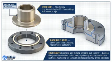
Lap Joint Flange
How it works:
A Lap Joint flange is a two-component system: a stub end (a short pipe section with a flanged collar, butt-welded directly to the pipe) paired with a loose backing flange that slides freely over the pipe and rotates around it.
The backing flange is bolted to the mating flange, pressing against the back of the stub end to transmit pressure. No welding touches the backing flange itself.
Best applications:
The rotating backing flange eliminates bolt-hole alignment headaches, a real advantage in:
- Cramped piping arrangements or field installations with tight access
- Corrosive services where only the stub end requires expensive alloy material — the backing flange stays standard carbon steel
For projects handling aggressive fluids, that material split can reduce flange costs substantially without compromising integrity.
Key limitation:
Lap Joint flanges have a lower pressure rating than Weld Neck flanges (similar to Slip-On class). The backing flange can slide, rotate, and wear over time if not properly managed. The two-part system also adds complexity to inventory management and installation sequencing compared to single-piece flanges.
How to Choose the Right Flange Type for Your Oil & Gas Application
Flange selection should be driven by operating conditions first — specifically the pressure class (ASME Class 150 through 2500) and temperature range. These parameters immediately narrow the viable options. For example, anything above Class 600 in a cyclic or high-fatigue service defaults to Weld Neck; anything requiring no welding defaults to Threaded or Lap Joint.
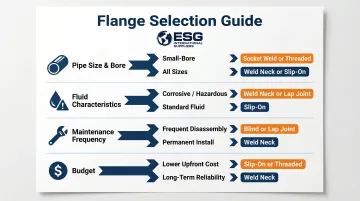
Four practical decision factors:
1. Pipe size and bore
- Socket Weld and Threaded flanges are limited to small-bore
- Weld Neck and Slip-On work across all sizes
2. Fluid characteristics
- Corrosive or hazardous media demand full-penetration welds (Weld Neck) or compatible alloy stub ends (Lap Joint)
- Sour service requires NACE MR0175/ISO 15156 compliance with strict metallurgical limits
3. Maintenance and access frequency
- Systems requiring frequent disassembly benefit from Blind or Lap Joint flanges
- Permanent installations suit Weld Neck configurations
4. Budget constraints
- Slip-On and Threaded flanges cost less upfront but may carry long-term reliability trade-offs in demanding services
Once you've matched a flange type to your operating conditions, the face type becomes the next decision — and it's equally application-specific.
Flange Face Type
Raised face (RF) is the standard for most ASME B16.5 applications. Ring Type Joint (RTJ) faces are required for the highest pressure/temperature combinations, where a metal-to-metal seal is essential. This choice is separate from but linked to the flange body type selected.
If you need help matching flange specifications — body type, face type, pressure class, and material grade — ESG International Suppliers stocks a broad range of flanges and fittings for oil and gas procurement across North and South America.
Common Flange Selection Mistakes to Avoid
Three mistakes account for the majority of flange failures and unplanned shutdowns in oil and gas piping systems.
Selecting based on cost alone. Downgrading from Weld Neck to Slip-On in high-pressure or cyclic service to cut procurement spend is a costly trade-off. The resulting fatigue failures or leaks generate downtime costs that far exceed the initial savings.
Ignoring fluid compatibility and corrosion risk. A sulfide stress cracking incident at a column overhead piping system resulted from material hardness exceeding NACE MR0175 limits at a pipe-to-flange welded joint. Specifying carbon steel in hydrogen sulfide or chloride-bearing service without checking material compatibility can lead to rapid crevice corrosion or stress cracking. Always cross-reference NACE MR0175/ISO 15156 for sour service applications.
Overlooking disassembly access during design. Flanges welded in place without any plan for future removal limit inspection access and complicate future repairs. Blind flanges and Lap Joint configurations should be built into the design wherever isolation, inspection, or periodic equipment removal is anticipated.
Conclusion
Flanges are foundational components in oil and gas piping systems. The six types covered — Weld Neck, Slip-On, Blind, Threaded, Socket Weld, and Lap Joint — each serve a distinct purpose determined by pressure, temperature, pipe size, fluid type, and maintenance requirements.
No single flange type suits all applications. Matching the right flange to its operating conditions is an engineering decision — get it wrong, and you're looking at leaks, unplanned downtime, or costly replacements. Get it right, and the system runs reliably for the full life of the installation. If you're sourcing flanges or fittings for an oil and gas project, ESG International Suppliers carries a broad range of industrial fittings and piping components for exactly these applications.
Frequently Asked Questions
What are the most common types of flanges used in the oil and gas industry?
The six most common types are Weld Neck, Slip-On, Blind, Threaded, Socket Weld, and Lap Joint — each standardized under ASME B16.5 and selected based on pressure class, pipe size, temperature, and fluid service requirements.
Which type of flange is used in high-pressure services?
Weld Neck flanges are the primary choice for high-pressure and high-temperature services due to their tapered hub and full-penetration butt weld, which distributes stress evenly. Blind flanges are also rated for high-pressure isolation across all ASME pressure classes.
Which flange face is most common in oil and gas?
The Raised Face (RF) is the most widely used flange face in oil and gas under ASME B16.5, compatible with spiral-wound and ring gaskets. Ring Type Joint (RTJ) faces are used in the highest-pressure and highest-temperature applications where a metal-to-metal seal is required.
What is a flange connection in the oil and gas industry?
A flange connection is a bolted joint between two mating flanges with a gasket compressed between their faces. It connects pipes, valves, pumps, or vessels, creating a pressure-rated, disassemblable joint for maintenance or inspection.
What is the purpose of a flange in the oil and gas industry?
Flanges provide a secure, leak-resistant connection between piping components and allow controlled disassembly for maintenance. They also enable isolation or inspection of specific sections, making them essential to safe and efficient facility operation.
What is a pipeline flange?
A pipeline flange is a flange used specifically to connect segments of a pipeline or to attach pipeline valves, instruments, and equipment. These flanges must meet the pressure, temperature, and material requirements of the fluid being transported and comply with applicable ASME or API standards.