Introduction
In oil and gas operations, valves are not interchangeable. Across upstream wellhead operations, midstream pipeline transport, and downstream refining facilities, they perform critical safety and process control functions under extreme pressures, temperature swings, and exposure to corrosive media like H₂S-rich crude oil.
Selecting the wrong valve type for a given application can trigger catastrophic consequences. At the Valero Meraux refinery, a 20-inch outlet valve rated for 275 psi failed under 2,100 psi after a relief valve malfunction, releasing 49,000 pounds of highly flammable hydrogen and hydrocarbon vapor. The resulting explosion is a stark example of what valve misapplication can cause.
Equipment failure remains a leading cause of pipeline incidents tracked by PHMSA. The cost extends beyond safety: premature seat erosion, unplanned downtime, and cross-contamination risks all stem from using the wrong valve in the wrong place.
This article covers the six essential valve types used in oil and gas, what makes each one unique, and how to match valve function to your specific operating conditions: whether you're managing upstream HPHT wells at 15,000 psi and 350°F, midstream pipeline isolation, or downstream process control.
Key Takeaways
- Valves control flow, pressure, and direction in oil and gas pipelines—selecting the wrong type causes operational failures and safety incidents
- The six essential types are ball, gate, globe, check, butterfly, and pressure safety valves, each designed for a distinct function
- Each type serves a specific role: isolation, throttling, backflow prevention, large-line flow control, or overpressure protection
- Selection depends on operating pressure, media type, temperature range, and whether throttling or isolation is required
- Matching valve type to function, rather than defaulting to the familiar or cheapest option, directly impacts equipment life and safety compliance
What Are Valves and Why Do They Matter in Oil & Gas?
A valve is a mechanical device that opens, closes, or partially obstructs a passageway to control the flow, pressure, or direction of fluids and gases within a piping system. In oil and gas, valves serve distinct functions depending on the operational phase: upstream valves manage wellhead pressure and production control, midstream valves provide pipeline isolation and emergency shutoff, and downstream valves regulate flow and temperature in refining processes. Using the wrong valve in a given phase leads to inefficiency, equipment damage, or safety incidents.
The global industrial valves market was valued at $80.4 billion in 2025 and is projected to reach $126.4 billion by 2033, with oil and gas driving a significant share of that demand. A single 460,000-bpd Gulf Coast refinery can evaluate over 300 control valves during one turnaround cycle — a figure that underscores how valve density in this sector is unusually high compared to most other industries.
The consequences of poor valve selection include:
- Pressure surges that exceed equipment ratings
- Cross-contamination when backflow occurs
- Seal failures from improper material selection
- Safety incidents including explosions and toxic releases
Oil and gas environments impose extreme demands: upstream HPHT (high-pressure, high-temperature) wells routinely expose valves to pressures between 10,000 and 20,000 psi and temperatures from 300°F to 400°F. Sour service environments containing H₂S require strict adherence to NACE MR0175 / ISO 15156 to prevent Sulfide Stress Cracking (SSC).
Each valve type is engineered with specific tolerances for its role: gate valves handle full-bore isolation, globe valves enable precise throttling, and safety valves provide overpressure protection when system limits are breached.
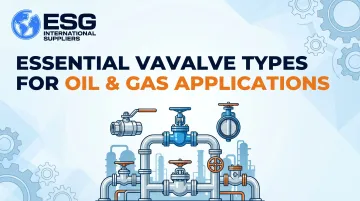
Essential Valve Types for Oil & Gas Applications
No single valve type suits all oil and gas applications. Different process requirements, pressure ratings, and media types demand specific valve designs. The six valve types covered below represent the essential categories that together address the full spectrum of flow control, isolation, regulation, and safety functions required across oil and gas operations.
Ball Valves
A ball valve is a quarter-turn rotational valve that uses a hollow, perforated ball to control flow. When the hole through the ball aligns with the pipe, flow is open; when rotated 90°, the ball blocks the passage completely, providing fast, reliable shutoff with minimal pressure drop.
What distinguishes ball valves:
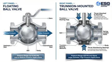
Ball valves handle both gas and liquid media across a wide temperature range and are available in two primary configurations. Floating ball valves suit low-to-medium pressure applications, where line pressure pushes the ball against the downstream seat to create a seal. Trunnion-mounted ball valves mechanically anchor the ball with bearings, absorbing line thrust and preventing excess friction—this design is required for large-diameter, high-pressure applications where operating torque must remain manageable.
Temperature capabilities by seat material:
| Seating Material | Max Operating Temp | Typical Use |
|---|---|---|
| PTFE | 200°C (392°F) | Standard hydrocarbon service |
| PEEK | 270°C (518°F) | High-pressure, moderate-temperature service |
| Metal-Seated (Stellite) | 500°C (932°F) | High-temperature, abrasive, fire-safe service |
Best use cases:
- Fast on/off shutoff in gas transmission lines
- Wellhead operations and subsea manifolds
- Offshore platform systems where tight sealing with low actuation torque is required
- Emergency shutdown (ESD) systems and LNG storage
Key trade-off: Ball valves offer excellent shutoff but lack throttling capability. Using them in a partially open position for flow regulation causes seat erosion and shortens valve life dramatically. They are strictly for isolation, not modulation.
Gate Valves
A gate valve is a linear motion valve that uses a sliding gate (disc) to fully open or fully close a flow path. When fully open, the gate retracts entirely from the flow stream, creating an unobstructed, straight-through passage ideal for fluids like crude oil that benefit from unrestricted flow.
What sets gate valves apart:
Gate valves are designed for full-bore, bidirectional isolation with minimal flow restriction. They feature an obturator that moves perpendicular to the direction of flow, and when fully retracted, the valve provides a clear bore with virtually no pressure drop. They are not suited for throttling and should only be operated fully open or fully closed.
Primary governing standards:
- API 600: Heavy-duty, bolted bonnet steel gate valves for petroleum refining
- API 602: Compact forged gate valves for sizes NPS 4 and smaller
- API 6D: Pipeline gate valves for midstream applications
Best use cases:
- Isolation points in pipeline systems
- Wellhead equipment and Christmas tree assemblies
- Refinery headers where the valve remains either fully open or fully shut for extended periods
- Applications where unrestricted flow is a priority
Key trade-off: Gate valves operate slowly and are not suited for emergency shutoff. They also require significant vertical clearance for the rising stem, limiting use in confined spaces.
Partial operation is a costly error: fluid accelerates to high velocity through the narrowed opening, creating a jet that causes severe disc vibration and "wire drawing"—erosion of the seating surfaces that leads to premature valve failure.
Globe Valves
A globe valve is a linear motion valve with an S-shaped internal flow path and a movable plug that seats against a stationary ring. Raising or lowering the plug changes the size of the opening, allowing precise flow control.
What distinguishes globe valves:
Unlike gate or ball valves, globe valves are specifically designed for throttling and regulation. The globular-shaped cavity minimizes seat erosion during modulation, and API 623 requires fully body-guided discs to support hydraulic forces and vibrations during severe throttling. This makes globe valves the preferred choice in process control systems where flow rate must be adjusted regularly rather than simply started or stopped.
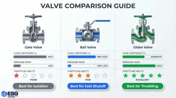
Flow characteristics comparison:
| Valve Type | Flow Coefficient (Cv) | Pressure Drop | Throttling Ability |
|---|---|---|---|
| Gate Valve | High (e.g., 300 for DN100) | Very Low (0.1 bar) | Poor |
| Ball Valve | Highest | Very Low | Fair (V-port: Good) |
| Globe Valve | Low (e.g., 100 for DN100) | High (1.6 bar) | Excellent |
Best use cases:
- Cooling water systems
- Fuel oil transport
- Turbine lube oil systems
- Any application where flow rate needs to be adjusted regularly rather than simply started or stopped
Key trade-off: Globe valves create a higher pressure drop than gate or ball valves due to their internal S-shaped passageway. They also require greater force to close under high-pressure conditions and are not ideal for high-flow, low-restriction applications. While gate valves have lower total cost of ownership in isolation service due to minimal pressure drop, misapplying a globe valve for simple isolation incurs severe energy penalties—potentially $9,500 more in pump energy costs over 10 years.
Check Valves
A check valve is an automatic, non-return valve that allows flow in only one direction and closes immediately when flow reverses. It requires no actuator or manual operation—fluid pressure itself opens and closes the valve.
What makes check valves unique:
Check valves are the only valve type that functions automatically without external actuation, making them essential for protecting pumps, compressors, and other equipment from damage caused by backflow. They have an obturator that responds automatically to block fluid in one direction and are self-actuating per ISO 14313.
Backflow damage mechanisms prevented:
- Pump reverse rotation
- Compressor bearing damage
- Destructive water hammer
Best use cases:
- Downstream of pumps and compressors in oil refineries and gas processing plants
- Applications where backflow would cause equipment damage
- Pipeline infrastructure where different media share the same system and cross-contamination must be prevented
Key trade-off: Check valves must be precisely sized for actual flow conditions—not simply matched to line size. Insufficient velocity or pressure drop causes "chatter" (rapid opening and closing), accelerating seat wear and eventual failure to block reverse flow. Sizing should target a minimum calculated pressure drop of 2 to 5 times the spring cracking pressure.
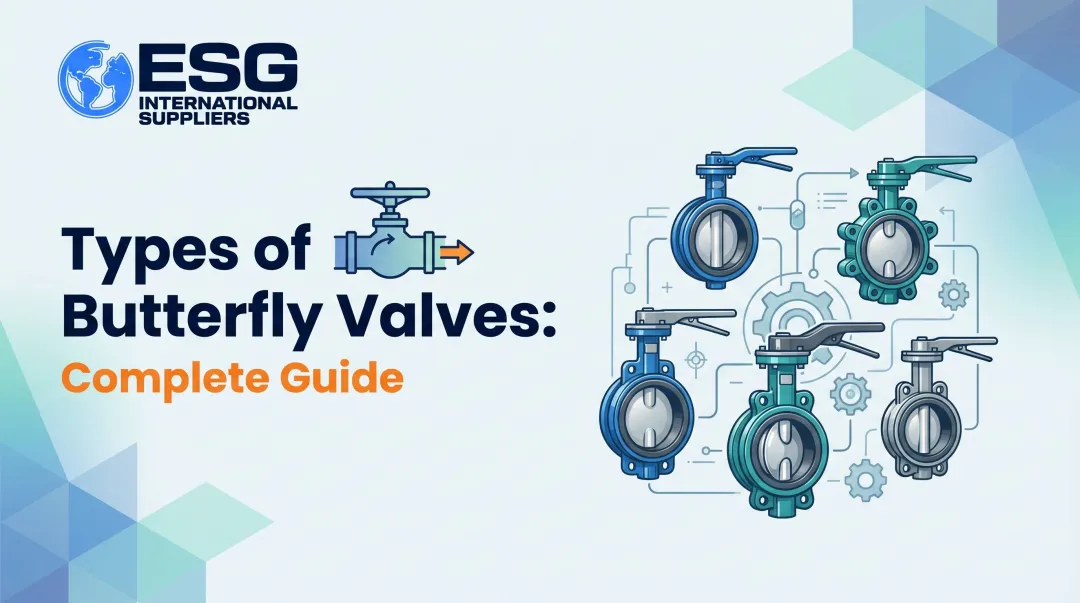
Butterfly Valves
A butterfly valve is a quarter-turn rotational valve that uses a circular disc (the "butterfly") held by a central rod to regulate flow. When the disc is parallel to the flow, the valve is open; when perpendicular, it is closed.
What distinguishes butterfly valves:
Their compact, lightweight design makes them well-suited for large-diameter pipelines (NPS 12 and above) where gate valves would be prohibitively heavy or expensive. A 12-inch butterfly valve can cost 60-70% less than an equivalent ball valve and weigh significantly less. High-performance triple offset valves (TOVs) can be up to 80% lighter than comparable ball valves, reducing installation complexity and structural support requirements.
Best use cases:
- Large-diameter pipelines in gas distribution
- Petrochemical facilities where space, weight, and cost are key considerations
- Bulk liquid storage and LNG transportation
- Flare systems and large-bore water/wastewater lines
Key trade-off: Butterfly valves are not ideal for high-pressure or high-temperature service. The disc remains in the flow path even when fully open, creating some flow resistance. Dynamic torque resulting from fluid flow must be calculated based on specific upstream/downstream conditions, and actuators must be sized accordingly—generic installation rules like "6 pipe diameters of straight run" don't account for application-specific turbulence that can accelerate wear.
Safety/Pressure Relief Valves (PSV and PRV)
Pressure safety valves (PSVs) and pressure relief valves (PRVs) are valves designed to automatically release pressure from a system when it exceeds a safe threshold, protecting vessels, pipelines, and equipment from overpressure failures.
Technical distinctions:
- Safety Valve (PSV): Characterized by rapid, full opening or "pop action." Designed primarily for compressible fluids (steam, gas, air).
- Relief Valve (PRV): Characterized by gradual or proportional opening as pressure increases. Designed strictly for incompressible media (liquids) to prevent damaging water hammer.
- Safety Relief Valve: A hybrid design that can function as a pop-action valve for gas or a proportional valve for liquids.
The terms are often used interchangeably in the field, but the distinction is operationally significant—applying a PRV to gas service or a PSV to liquid service creates serious safety risks.
What sets safety valves apart:
They are passive safety devices that do not control flow in normal operations but activate automatically in emergencies, making them non-negotiable components in any pressurized oil and gas system. ASME BPVC Section VIII (UG-125) mandates that all pressure vessels, irrespective of size or pressure, shall be provided with pressure relief devices.
Primary governing standards:
- API 520 (Parts I & II): Sizing, selection, and installation of pressure-relieving devices
- API 521: Guide for pressure-relieving and depressuring systems
- ASME BPVC Section VIII: Rules for construction of pressure vessels, including overpressure protection requirements
Best use cases:
- Storage vessels, wellheads, separators, and pipelines wherever overpressure poses an explosion or blowout risk
- Required by code in virtually all oil and gas facilities
Key trade-off: Safety valves must be regularly tested and calibrated to ensure they activate at the correct set pressure. A valve that opens too early causes unnecessary process interruptions, while one that is stuck or set too high creates a catastrophic safety risk. At a Kinder Morgan facility, a stuck-open dump valve caused ice/hydrate to block a relief path, leading to the catastrophic rupture of a drain system vessel and the release of 5.6 million pounds of carbon dioxide and 111,000 pounds of natural gas.
How to Choose the Right Valve for Your Application
The "right" valve is determined by function first. Isolating flow, regulating flow, preventing backflow, and providing safety relief are four fundamentally different requirements, and each maps to a different valve type. Matching valve function to operational intent is the starting point before any other consideration.
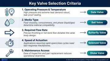
Key operational factors to evaluate:
- Operating pressure and temperature range: Verify valve ratings align with actual field conditions, not just theoretical design conditions. Ultra-HPHT wells can reach 15,000 to 20,000 psi and temperatures exceeding 350°F.
- Media type: Gas, liquid, slurry, or corrosive fluid (e.g., H₂S-rich crude requiring NACE MR0175 compliance).
- Required flow rate: Full-bore isolation or throttled flow control.
- Speed of actuation: Emergency shutoff requires quarter-turn valves like ball or butterfly; slow process control suits globe valves.
- Maintenance access: Gate valves require vertical clearance for rising stems; butterfly valves are compact and lightweight.
Material and standards considerations:
Valves for oil and gas must meet industry standards specific to the application:
- API 6A: Specification for wellhead and Christmas tree equipment
- API 6D: Pipeline and piping valves (ball, check, gate, plug)
- API 600: Steel gate valves for petroleum refining
- ASME B16.34: Pressure-temperature ratings, dimensions, and materials for flanged, threaded, and welding end valves
Confirm which standard governs your application and verify that candidate valves are rated accordingly. For sour service environments with H₂S partial pressures exceeding 0.3 kPa (0.05 psi), standard carbon steels are highly susceptible to Sulfide Stress Cracking (SSC). Strict adherence to NACE MR0175 / ISO 15156 is required.
Expert sourcing support:
Given the number of standards, materials, and pressure ratings involved, sourcing the wrong valve is a costly mistake. ESG International Suppliers works with oil and gas operations across North and South America to match valve specifications to application requirements — covering material compatibility, pressure ratings, and standards compliance. Lead times on critical components matter, and ESG's team can help you avoid delays and selection errors before they reach the field.
Mistakes to Avoid When Selecting an Oil & Gas Valve
Even a correctly specified valve can fail prematurely when common selection mistakes go unchecked. These four errors account for a large share of unplanned valve replacements in oil and gas operations.
Throttling with an isolation valve
Operating a gate valve in a partially open position to regulate flow accelerates seat and disc wear, creates leak paths, and forces premature replacement. Gate valves and ball valves are isolation devices only — globe valves are the right choice for throttling service.
Choosing on upfront cost alone
A cheaper valve with poor material ratings will corrode, fail, or need frequent replacement — costing far more over its service life than a properly rated valve. Consider total cost of ownership: purchase price plus operating and maintenance costs across the asset's lifespan.
For example, a gate valve costs less upfront than a globe valve, but using a globe valve for simple isolation incurs energy penalties of up to $9,500 more in pump costs over 10 years due to higher pressure drop.
Ignoring pressure and temperature ratings for the actual media
A valve rated for water service can fail quickly on H₂S-rich crude or high-temperature steam condensate. Always verify material compatibility and pressure class against real field conditions:
- Soft-seated ball valves with PTFE seals degrade above 200°C (392°F)
- High-temperature service above that threshold requires metal-seated, surface-hardened valves rated up to 500°C (932°F)
- H₂S service requires NACE-compliant materials to resist sulfide stress cracking
Improperly sizing check valves
Sizing check valves by line size alone — without accounting for actual flow conditions — leads to insufficient velocity to keep the valve fully open. This causes rapid chatter and premature trim wear. Proper sizing requires a minimum calculated pressure drop of 2 to 5 times the spring cracking pressure.
Conclusion
Oil and gas operations span wildly different pressures, media types, flow requirements, and safety demands — no single valve design can handle all of them. Each of the six essential types covered here exists for specific reasons:
- Ball and gate valves provide reliable isolation for on/off service
- Globe valves enable precise flow throttling and regulation
- Check valves prevent backflow automatically without operator input
- Butterfly valves handle large-diameter, high-flow applications efficiently
- **Safety and pressure relief valves** protect systems against catastrophic overpressure
Valve selection must follow function, operating conditions, and applicable standards — not familiarity or purchase price alone. The right choice directly affects uptime, regulatory compliance, and maintenance costs across upstream wellhead operations, midstream pipeline transport, and downstream refining and processing.
Frequently Asked Questions
Which valves are used in the oil and gas industry?
The six most essential valve types in oil and gas are ball, gate, globe, check, butterfly, and pressure safety/relief valves. Each serves a specific function: ball and gate valves provide isolation, globe valves control flow rate through throttling, check valves prevent backflow automatically, butterfly valves suit large-diameter pipelines, and safety valves protect against overpressure events.
What is the use of ball valve in oil and gas industry?
For fast, reliable on/off shutoff in wellhead operations, subsea manifolds, and gas transmission lines, ball valves are the go-to choice. They seal tightly, require low torque, and handle temperatures from cryogenic to 500°C depending on seat material. Partial-open operation causes rapid seat erosion, so they are not suitable for throttling.
What is the purpose of a globe valve in a pipeline?
Globe valves are designed for throttling and flow regulation. Their S-shaped internal flow path allows operators to control flow rate precisely by raising or lowering the plug against a stationary ring, making them ideal for cooling water systems, fuel oil transport, turbine lube oil systems, and any application requiring fine flow adjustment rather than simple on/off control.
What are the control valves used in oil and gas industry?
In refining and processing, control valves regulate flow, pressure, and temperature in response to signals from a process controller. The category spans globe valves, butterfly valves, and specialized automated valves — globe valves handle precise throttling, while automated ball and butterfly valves manage remote on/off control.
What's the difference between PSV and PRV?
A PSV (Pressure Safety Valve) snaps fully open at a set pressure and is used primarily for gas and vapor service to rapidly relieve overpressure. A PRV (Pressure Relief Valve) opens gradually in proportion to overpressure and is used for liquid service to prevent damaging water hammer. The distinction matters for proper sizing and application, even though the terms are often used interchangeably on-site.
How does a gas safety valve work?
A PSV is held closed by a spring calibrated to a specific pressure set point. When system pressure exceeds that threshold, gas pressure overcomes the spring force and the valve pops open to release the buildup. It closes automatically once pressure drops back below the set point, providing continuous overpressure protection without manual intervention.