Introduction
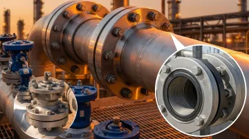
Flanges are essential connectors in industrial piping systems, and weld neck and slip-on are two of the most widely specified types. Yet they serve very different purposes—and choosing the wrong one can lead to system failure, costly rework, or serious safety risks.
In demanding sectors like oil & gas, power generation, and mining, this decision carries operational and financial consequences that compound over a system's lifespan. A flange that looks identical on a specification sheet can perform entirely differently under pressure, temperature swings, or cyclic loading — affecting everything from installation cost to long-term reliability.
This guide breaks down the structural and performance differences between weld neck and slip-on flanges — covering pressure ratings, installation requirements, cost tradeoffs, and which applications each type is best suited for.
Key Takeaways
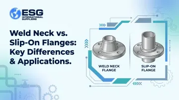
- Weld neck flanges feature a tapered hub and full-penetration butt weld; slip-on flanges slide over the pipe and use fillet welds
- Weld neck flanges excel in high-pressure, high-temperature, and high-stress environments; slip-on flanges suit low-to-moderate pressure applications
- Slip-on flanges cost 20-30% less upfront but require two welds and two inspections, narrowing the installed cost gap
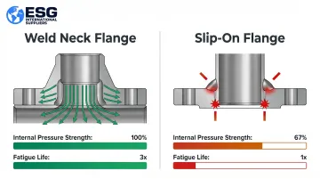
- Slip-on flanges deliver roughly two-thirds the internal pressure strength and one-third the fatigue life of weld neck flanges (ASME B16.5 SO Flanges reference)
- Operating conditions and lifecycle cost—not just unit price—should drive your specification decision
Weld Neck vs. Slip-On Flanges: Quick Comparison
| Attribute | Weld Neck Flange | Slip-On Flange |
|---|---|---|
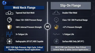
| Initial Cost | Higher (20-30% more) | Lower |
| Design Structure | Tapered hub integrated with pipe bore | Plain bore slides over pipe |
| Welding Method | Single full-penetration butt weld (Class B) | Double fillet weld (Class C) |
| Nominal Pressure Range | 1–25 MPa (Class 150–2500) | 0.6–4.0 MPa (Class 150–300 practical limit) |
| Fatigue Life | Superior (3x longer than SO) | Lower (1/3 of WN) |
| Internal Pressure Strength | 100% rated capacity | ~67% of WN flange |
| NDE Method | Radiographic or ultrasonic (volumetric) | Surface only (PT/MT) |
| Typical Applications | High-pressure pipelines, refineries, offshore, steam systems | Water systems, HVAC, low-pressure utilities |
Both flange types are manufactured to ASME B16.5 and B16.47 standards, meaning they share the same bolt patterns and pressure classes on paper. Their structural performance under those ratings, however, diverges in practice. Because both types look similar and follow the same dimensional specifications, some engineers assume they are interchangeable. In high-cycle or elevated-temperature service, that substitution can lead to fatigue cracking at the weld zone or pressure exceedance beyond the slip-on flange's effective load capacity.
What is a Weld Neck Flange?
A weld neck (WN) flange is distinguished by a long, tapered hub that gradually transitions from the flange body to the pipe wall. It joins to the pipe using a full-penetration butt weld (girth weld), classified as a Class B weld and subject to radiographic inspection. Full joint penetration — versus the fillet welds used on slip-on flanges — is what gives WN flanges their structural advantage in demanding service conditions.
Structural Benefits of the Tapered Hub
The tapered hub distributes stress evenly across the connection, eliminating the stress concentration that occurs at the base of other flange types. This design makes WN flanges highly resistant to:
- Bending moments from piping loads
- Line expansion and retraction caused by temperature swings
- Cyclic fatigue loading in dynamic systems
- High internal pressures sustained over long periods
Materials and Manufacturing
Weld neck flanges are typically machined from forged steel—carbon steel, alloy steel, or stainless steel—which gives them higher density and mechanical strength compared to plate-machined alternatives. This forging process supports their suitability for pressure ratings from Class 150 to Class 2500.
Operational Conditions for WN Flanges
Weld neck flanges are specified when systems demand:
- High-pressure pipelines (up to 25 MPa nominal)
- Extreme temperature environments (both elevated and subzero)
- Hazardous media where zero-leak tolerance is required (toxic, flammable, or corrosive fluids)
- Long-term installations where maintenance access is limited or downtime is costly
Use Cases of Weld Neck Flanges
Weld neck flanges dominate in:
- Oil and gas wellheads and transmission pipelines
- Petrochemical refineries processing hazardous fluids
- Power generation steam systems operating at high temperature and pressure
- High-pressure hydraulic systems in mining and heavy industry
- Offshore platforms operating under high-cycle fatigue, high-pressure, and corrosive seawater conditions
Unlike slip-on flanges, WN flanges connect directly to butt-welded fittings — elbows, tees, and reducers — without additional transition welds, which simplifies layout in complex piping configurations.
What is a Slip-On Flange?
A slip-on (SO) flange is a flat, ring-shaped flange with an inner diameter slightly larger than the outer diameter of the pipe. It slips over the pipe end and is secured in place before welding.
Installation requires two fillet welds — one on the outer face and one on the inner bore. These welds are classified as Class C seams, tested by magnetic particle or dye penetrant methods rather than radiography.
Structural Limitations of the Double-Weld Design
The double-weld approach creates redundancy, but it also introduces real structural tradeoffs:
- No full penetration: Fillet welds reduce load-bearing capacity compared to full-penetration butt welds
- Fatigue vulnerability: Stress concentrates at the weld toes, accelerating fatigue under cyclic loading
- Slip-on flanges carry roughly two-thirds the internal pressure strength and one-third the fatigue life of comparable weld neck flanges, according to flange engineering references
Material and Cost Profile
Slip-on flanges are machined from carbon steel, stainless steel, or alloy materials to ASME B16.5 specifications. Because the design requires less precision machining than a weld neck hub, they cost less to produce and stock.
This makes them a practical choice for lower-pressure, non-cyclic applications — particularly where installation speed and budget matter more than long-term fatigue resistance.